5 months ago the moon and stars aligned, which resulted in me walking past a Sansui 1000A on the curbside. 44 pounds of Japanese tube sound, out for the taking. 100 watts. People love to toss things away.
I have since gotten around to restoring it. One invaluable tool for the safe verification of antique and vintage audio equipment is the dim-bulb tester.
A dim-bulb tester is simply a light bulb wired in series between the Hot wire of your AC mains outlet and the equipment to be powered, e.g. a receiver or amplifier. It is effectively a current limiter. In the event of a short circuit, the bulb will shine bright instead of releasing magic smoke from your equipment.
The following diagram illustrates how I wired my dim-bulb tester:
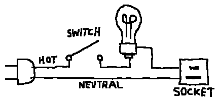
* Ground connection omitted for clarity. It is wired straight across. DO NOT reverse Hot and Neutral!
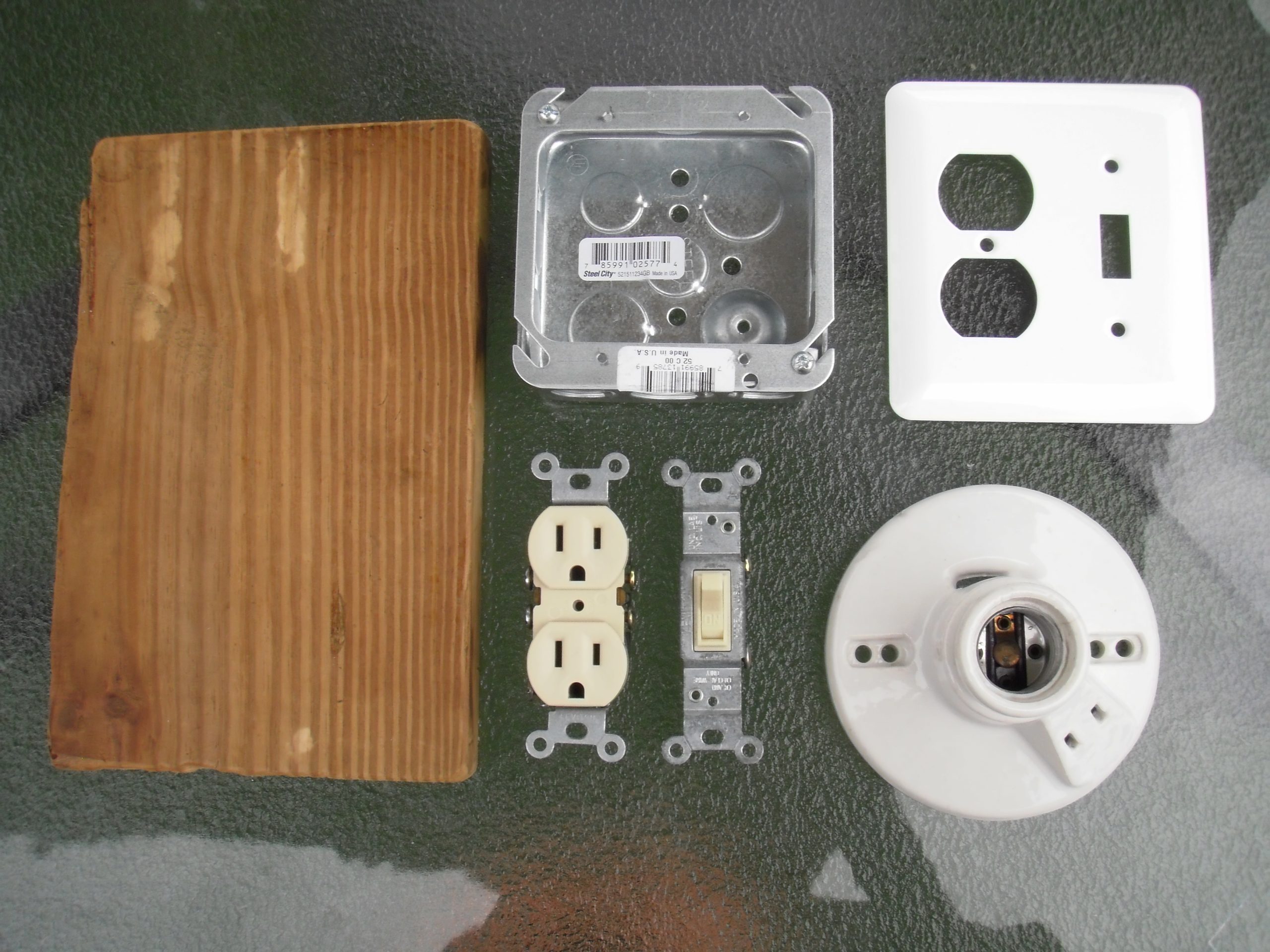
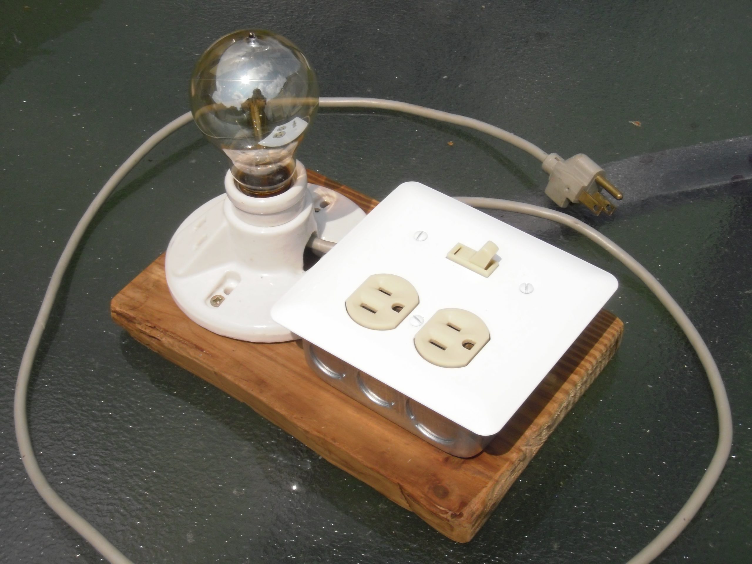
A dim-bulb tester can be assembled cheaply and easily from parts found at your local hardware store. Below is a photograph of the ingredients I chose. The mains connectors and associated bits/bobs pictured are specific to the Americas, although this information can be applied to electric systems in other countries.
I started by screwing the 2-gang junction box into a plank of wood, then placed the switch and sockets in position.
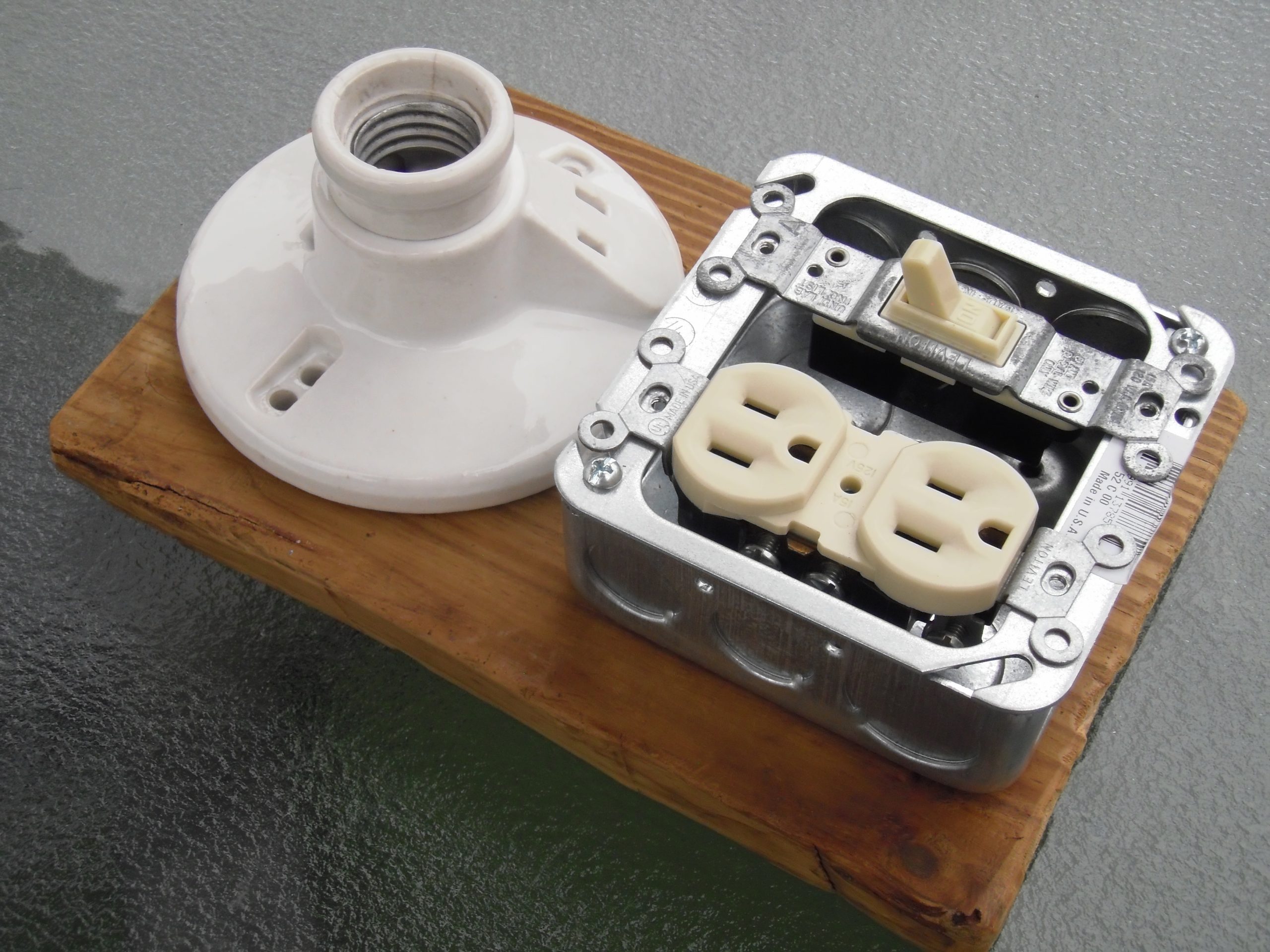
Next I wired everything together with an old 3-prong electrical cord.
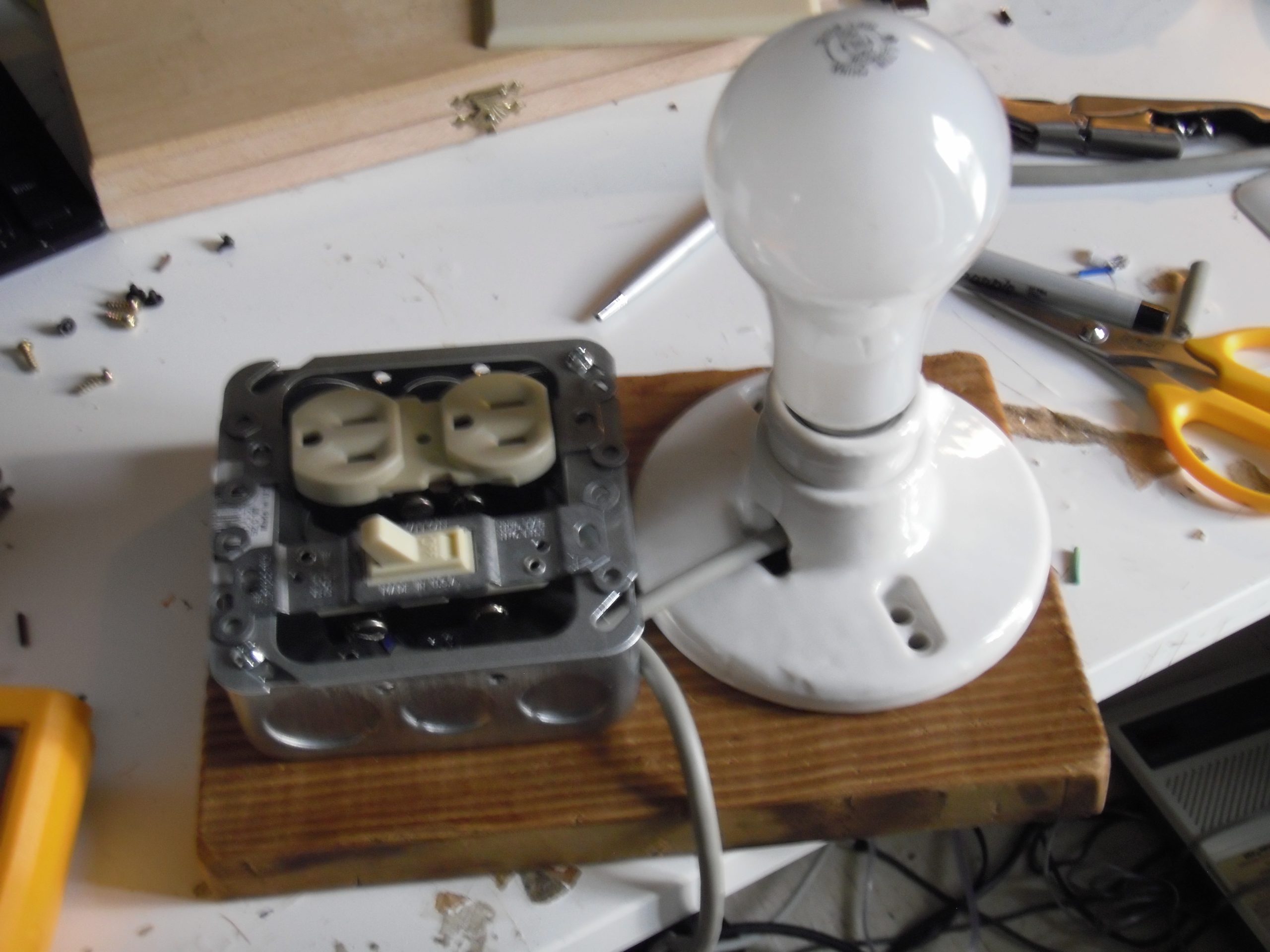
After that was done I screwed the light bulb socket into the wood, screwed the switch and duplex outlet into the junction box, and hid it all behind a face plate. I was very pleased with the result.
You may wish to read what I’ve already written, but from people who are smarter than me: